B-2231-UK-11-2013-REV. C
An
Company
Check that the specifications on the identification plate meet the require-
ments regarding pressure, temperature and media.
The piping must have a straight line and the flanges have to be parallel.
Furthermore there must be a distance between the flanges, corresponding
to the face-to-face dimensions of the butterfly valve.
The butterfly valve can be mounted in any direction. However if there are
a lot of dirt particles on the bottom of the pipe, it will be suitable to mount
the stem of the butterfly valve horizontally. This will protect the pivot point
of the disc.
Before commissioning, the pipe work has to be rinsed out to remove dirt
and remnants of welding material, to avoid damage on the liner. During the
rinsing procedure, the butterfly valve has to be positioned as open and may
not be operated, before the rinsing has been completed.
Welding operations may not be performed nearby the butterfly valve, as
welding drops can damage the liner.
Do not use gaskets. The liner works as sealing to the atmosphere.
Where vacuum, high flow rate or water hammering can occur, flanges with-
out a loose collar should be used, to obtain the best conditions.
Installation guide for
Butterfly Valves
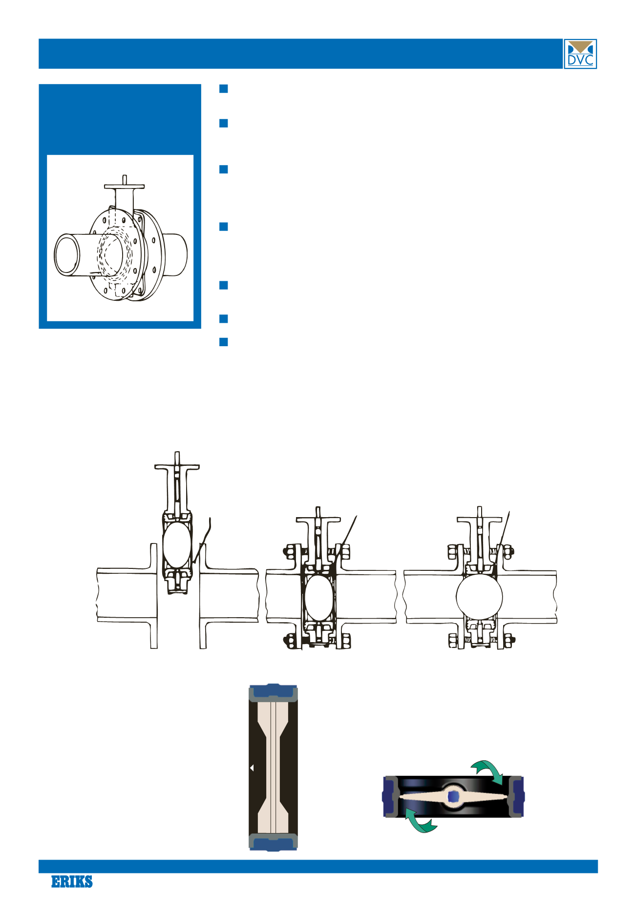
Carefully place the butterfly
valve between the flanges,
with the disc in closed posi-
tion.
Check that the flange covers
the area of the liner. Afterwards
tighten the bolt on the flange
by hand.
Carefully open and close the valve to check
that the disc centralizes and the disc does not
touch the flange. With the disc in the open
position, tighten crosswise with a wrench.
Though the valves are constructed to work as shown on the left,
counter clockwise rotation - CCW - can be applied without prob-
lems, if consider that the torque in this case will increase.
The best angle for a closed valve is 90
°
because of the special
design of the liner and rounded disk edge.
As the butterfly valves are
equipped with the unique wave
shaped liner, the operation of the
valves, either free stem, handle or
gear operated, has to follow the
guidelines as shown below.
A small triangular shaped figure is
placed on the liner - this triangle
indicates which way the disc has to
enter the liner.
Generally spoken the disc has to
rotate clockwise - CW - in order to
have the lowest possible torque -
and thus the longest possible life
time.
Installation guide
Turn disc CW
towards arrow
to close
Turn 90
°
CW to close
18
Know-how makes the difference


