Know-howmakes the difference
15
An
Company
B-1210-UK-02-2014-REV.B
*) Torque figures included 30% safety factor. (TEST: 0bar diff. pressure, ambient temperature, non-lubricated)
When dimensioning the actuator followingmust be added: - 15% if lubricatingmedias.
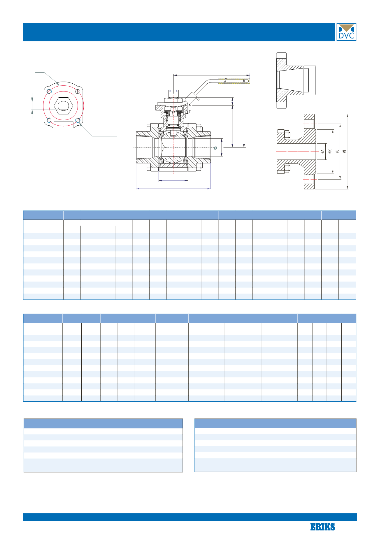
Dimensions type1211 steel and1311 stainless steel
E
øD
H
B1
B2
C
+0.8
+0.2
L2
L
-+1
ISO5211
F
Mx4
(G)
øD øG
ød øG
Dimension
Valvewithhandle
ISO topflange
Stem
[mm]
L [mm]
L2
B2
øC
E
H
ISO
5211
øM1 øX1x4 ISO
5211
øM2 øX2x4
F
B1
Gevind Svejse SMS Flange [mm]
[mm]
[mm]
[mm]
[mm]
[mm]
[mm]
[mm]
[mm]
[mm]
[mm]
DN08FB
75.0 75.0 75.0
-
24.5 42.6 11.5
139
77.0
F03
36
6.0
F04
42
6
9
7.6
DN10FB / DN15RB 75.0 75.0 75.0
-
24.5 42.6 12.6
139
77.0
F03
36
6.0
F04
42
6
9
7.6
DN15FB / DN20RB 72.5 75.0 75.0
130
24.5 42.6 15.0
139
77.0
F03
36
6.0
F04
42
6
9
7.6
DN20FB / DN25RB 85.4 90.0 90.0
150
31.4 46.9 20.0
139
82.0
F03
36
6.0
F04
42
6
9
8.6
DN25FB / DN32RB 105.3 110.0 110.0 160
41.3 59.3 25.0
165
98.5
F04
42
6.0
F05
50
7
11
10.4
DN32FB / DN40RB 111.0 115.0 115.0 180
48.4 62.6 32.0
165 102.0 F04
42
6.0
F05
50
7
11
10.4
DN40FB / DN50RB 127.3 129.6 129.6 200
56.3 79.0 38.0
215 128.0 F05
50
6.0
F07
70
9
14
13.4
DN50FB / DN65RB 145.0 145.0 145.0 230
71.4 87.7 50.0
215 137.0 F05
50
7.5
F07
70
9
14
13.4
DN65FB / DN80RB 185.0 185.0 185.0 290
86.6 108.7 65.0
262 167.0 F07
70
7.5
F10
102
12
17
16.8
DN80FB / DN100RB 205.0 205.0 205.0 310
99.0 117.7 76.0
262 176.0 F07
70
10.0
F10
102
12
17
17.8
DN 100FB
240.0 240.0 240.0 350 127.0 133.7 100
312 192.0 F07
70
10.0
F10
102
12
17
16.8
Dimension *) Torque
Weight
Kv-value
Buttweld ends
Flange ends
[mm]
[inch]
FB
[Nm]
RB
[Nm]
FB
[kg]
RB
[kg]
FB flanger
[kg]
90°m³/t
Type 1211
Type 1311
SMS3008
øA
[mm]
øK
[mm]
øJ
[mm]
øI
[mm]
FB
RB
øG / ød (mm)
øG / ød (mm)
øG / ød (mm)
DN08
1/4”
11
-
0.89
-
-
6.9
-
13.7 / 7.3 (3.2)
13.5 / 10.3 (1.6)
10.0 / 8.0 (1.0)
-
-
-
-
DN10
3/8”
11
-
0.88
-
-
6.9
-
17.5 / 11.1 (3.2)
17.2 / 14.0 (1.6)
12.0 / 10.0 (1.0)
-
-
-
-
DN15
1/2”
11
11
0.82 0.84
2.34
12.7
6.9
21.3 / 14.9 (3.2)
21.3 / 18.1 (1.6)
18.0 / 16.0 (1.0)
15
45
65
95
DN20
3/4”
14
11
1.29 0.85
3.47
29.2 12.7 26.9 / 20.5 (3.2)
26.9 / 23.7 (1.6)
25.0 / 22.6 (1.2)
20
58
75 105
DN25
1”
20
14
2.01 1.41
4.66
48.2 29.2 33.7 / 25.7 (4.0)
33.7 / 29.7 (2.0)
32.0 / 29.6 (1.2)
25
68
85 115
DN32
1 1/4”
31
20
2.76 2.17
6.63
73.1 48.2 42.4 / 34.4 (4.0)
42.4 / 38.4 (2.0)
33.7 / 31.3 (1.2)
32
78 100 140
DN40
1 1/2”
42
31
4.21 2.87
8.64
107.5 73.1 48.3 / 40.3 (4.0)
48.3 / 44.3 (2.0)
38.0 / 35.6 (1.2)
38
88 110 150
DN50
2”
59
42
5.83 4.49
12.20
215.0 107.5 60.3 / 51.3 (4.5)
60.3 / 56.3 (2.0)
51.0 / 48.6 (1.2)
50 102 125 165
DN65
2 1/2”
82
59
11.00 6.94
21.00
275.2 215.0 76.1 / 67.1 (4.5)
76.1 / 70.9 (2.6)
63.5 / 60.3 (1.6)
65 122 145 185
DN80
3”
121
82
14.78 12.64 28.90
498.8 275.2 88.9 / 78.9 (5.0)
88.9 / 83.7 (2.6)
76.1 / 72.9 (1.6)
80 138 160 200
DN100
4”
149
121
23.30 16.00 40.05 877.2 498.8 114.3 / 103.1 (5.6) 114.3 / 109.1 (2.6) 101.6 / 97.6 (2.0)
100 162 190 235
MEDIA FACTOR
MULTIPLIER
Clean, particle free, non-lubricating (water, alcohol, etc)
1.00
Clean, particle free, lubricating (oils, hydraulic fluid, etc)
0.80
Slurries or heavily corroded, solvents and contaminated systems
2.00#
Gas or saturated steam, clean andwet
1.00
Gas or superheated steam, clean and dry
1.30
Gas, dirty unfiltered e.g. natural gas, Chlorine
1.50
Basic Torque*Media Factor *Service Factor = Sizing Torque
#Usingball valves in contaminated systemswill reduce life time
SERVICE FACTOR
MULTIPLIER
Simple On andOff Operations
1.00
Throttling
1.20
Positioner Control
1.50
Once per day Operations
1.20
Once every two days or a “Plant Critical” Operation
1.50
Max differential pressure
(DN08-32 PN125) 1.50
(DN40-65 PN100) 2.00
(DN80-100 PN69) 2.80


