14
Know-howmakes the difference
B-1210-UK-02-2014-REV.B
An
Company
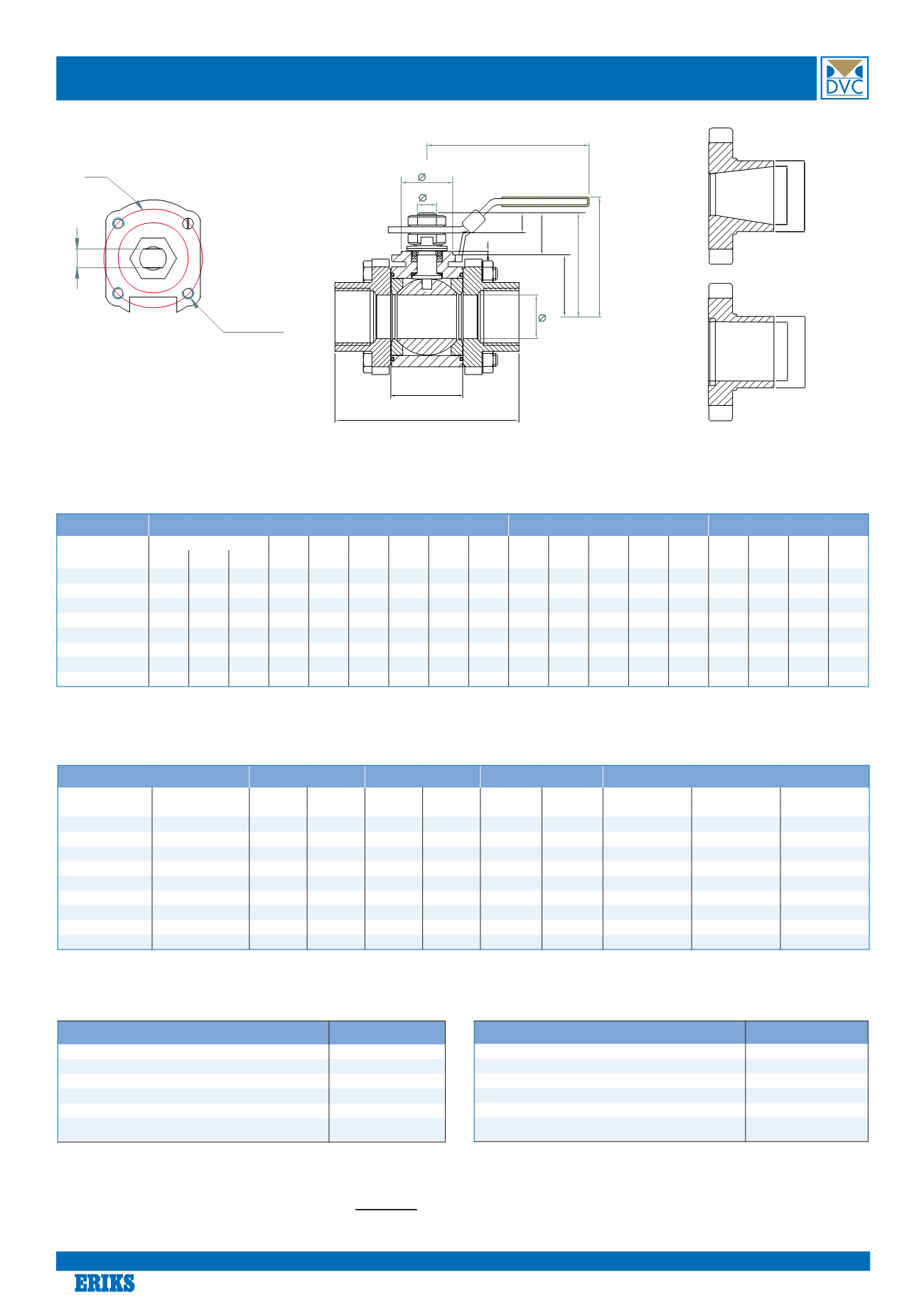
Dimensions type1210 steel and1310 stainless steel
L
H
H1
B2
B1
B4
B3
E
D
C
K
L2
ISO5211
F
Mx4
(G)
*) Torque figures include 30% safety factor. (TEST: 0bar diff. pressure, ambient temperature, non-lubricating)
When dimensioning the actuator followingmust be added:
ød øG
ød øG
Dimension
valvewithhandle
iso topflange
stem
[mm]
L [mm]
L2
B2
øC
E
H
H1
ISO
5211
G
K
Mx4
B3
øD
F
B1
B4
Thread BW SMS [mm]
[mm]
[mm]
[mm]
[mm]
[mm]
[mm]
[mm]
[mm]
[mm]
[mm]
[mm]
[mm]
[mm]
DN08FB
64,8 64,8 64,8 24.5 29,8
10
134 64,3 37,2 F03
36
25
M5
0,5
9,5
6,5
7,4
6,1
DN10FB / DN15RB 64.8 64.8 64.8 24.5 29.8
10
134 64.3 37.2 F03
36
25
M5
0.5
9.5
6.5
7.4
6.1
DN15FB / DN20RB 72.5 75.0 75.0 24.5 29.0
15
134 71.5 45.1 F03
36
25
M5
2.0
9.5
6.5
16.1
7.3
DN20FB / DN25RB 85.4 89.8 89.8 31.4 33.0
20
134 76.0 51.1 F03
36
25
M5
2.0
9.5
6.5
18.1
8.8
DN25FB / DN32RB 105.3 109.4 109.4 41.3 36.0
25
170 82.3 60.6 F04
42
30
M5
2.0
11.1
8.0
24.6 11.0
DN32FB / DN40RB 111.0 114.4 114.4 48.4 40.0
32
170 87.3 64.3 F04
42
30
M5
2.0
11.1
8.0
24.3
9.7
DN40FB / DN50RB 127.3 130.0 130.0 56.3 47.3
38
207 103.6 77.5 F05
50
35
M6
2.0
14.3
9.7
30.2 12.2
DN50FB / DN 65RB 145.0 145.0 145.0 71.4 69.5
50
207 121.6 95.0 F05
50
35
M6
2.0
14.3
9.7
30.2 12.2
Dimension
*) Basic Torque
Weight
kv-values
Buttweld ends
[mm]
[inch]
FB [Nm]
RB [Nm]
FB [kg]
RB [kg]
FB 90°m³/t RB 90°m³/t
Type 1210
Type 1310
SMS3008
øG xmm (ød)
øG xmm (ød)
øG xmm (ød)
DN08
1/4”
9.6
-
0.80
-
6.9
-
13.7 x 3.2 (7.3)
13.5 x 1.6 (10.3)
10.0 x 1.0 (8.0)
DN10
3/8”
9.6
9.6
0.80
0.66
6.9
6.9
17.5 x 3.2 (11.1)
17.2 x 1.6 (14.0)
12.0 x 1.0 (10.0)
DN15
1/2”
10.8
9.6
0.82
0.66
12.7
6.9
21.3 x 3.2 (14.9)
21.3 x 1.6 (18.1)
18.0 x 1.0 (16.0)
DN20
3/4”
14.4
10.8
1.28
0.87
29.2
12.7
26.9 x 3.2 (20.5)
26.9 x 1.6 (23.7)
25.0 x 1.2 (22.6)
DN25
1”
19.2
14.4
2.07
1.36
48.2
29.2
33.7 x 4.0 (25.7)
33.7 x 2.0 (29.7)
32.0 x 1.2 (29.6)
DN32
1 1/4”
31.2
19.2
2.65
2.01
73.1
48.2
42.4 x 4.0 (34.4)
42.4 x 2.0 (38.4)
33.7 x 1.2 (31.3)
DN40
1 1/2”
40.8
31.2
3.79
2.69
107.5
73.1
48.3 x 4.0 (40.3)
48.3 x 2.0 (44.3)
38.0 x 1.2 (35.6)
DN50
2”
57.6
40.8
5.51
4.04
215.0
107.5
60.3 x 4.5 (51.3)
60.3 x 2.0 (56.3)
51.0 x 1.2 (48.6)
DN65
2 1/2”
-
57.6
-
6.78
-
215.0
76.1 x 4.5 (67.1)
76.1 x 2.6 (70.9)
63.5 x 1.6 (60.3)
MEDIA FACTOR
MULTIPLIER
Clean, particle free, non-lubricating (water, alcohol, etc)
1.00
Clean, particle free, lubricating (oils, hydraulic fluid, etc)
0.80
Slurries or heavily corroded, solvents and contaminated systems
2.00#
Gas or saturated steam, clean andwet
1.00
Gas or superheated steam, clean and dry
1.30
Gas, dirty unfiltered e.g. natural gas, Chlorine
1.50
Basic Torque*Media Factor *Service Factor = Sizing Torque
SERVICE FACTOR
MULTIPLIER
Simple On andOff Operations
1.00
Throttling
1.20
Positioner Control
1.50
Once per day Operations
1.20
Once every two days or a “Plant Critical” Operation
1.50
Max differential pressure
(DN08-32 PN125) 1.50
(DN40-65 PN100) 2.00
EXAMPLE:
1310DN25FB, Natural gas, Positioner Control.
19,2[Nm] *1.5*1.5=43.2Nm (Sizing Torque)
#Usingball valves in contaminated systemswill reduce life time


